
In this chapter, we talk about x-ray tube components and their roles and types further.
Focal Spot Size
The focal spot size is the area of the anode, where electrons are struck off, and is made up of tungsten, here, the electron beam is directly influenced by these two characteristics are followings;
- What is the dimension of the filament coil,
- How is the focusing cup made?
If the filament is longer, it will produce a wider shadow and a smaller filament resulting in a narrower shadow.

The heat dissipation is directly proportional to the size of the focal spot, the larger the focal spot area, the more heat is produced, conversely, a smaller focal spot area produces less heat in comparison with a larger focal spot area and this gives a better spatial resolution.
In routine radiography the focal spot size is typically ranging from 1.0mm to 1.2 mm and in the case of mammography, this size is small ranging from 0.3mm to 0.6mm to give better spatial resolution.
So, the focal spot in radiology is a very important part of the X-ray tube, as it impacts the final image.
Actual vs Effective Focal Spot
The focal spot size is divided into two sizes, are actual and effective focal spots.

Actual Focal Spot
The actual Focal Spot is the area where electrons are struck from the cathode, and it shows the electron beam from the cathode to the anode, where it strikes.
Effective Focal Spot
The effective focal spot is the projected area of the actual focal support as seen in the X-ray beam.
The angulation of diverse radiation towards the patients and uses for diagnostic purposes.
Relation between the Actual and Effective Focal Spot
The relation between the actual and effective focal spot is defined by this equation;
Effective Focus = Actual Focal Spot * sin θ
Here, θ represents the angle where x-rays are emitted at the focal spot. And this angle shows that the effective focal spot is always smaller than the actual focal spot area, because of this angulation.
Line Focus Principle
The line focus principle is the effective method to remove heat produced during the production of x-rays and maintain the image sharpness. This includes the angulation of the anode to dissipate heat properly.

It’s a connection between actual and effective focal spot sizes, and is described by the given equation;
Effective Focus = Actual Focal Spot * sin θ
By angulation of the target, the effective focal spot can be reduced without changing the actual focal spot size.
As we know, 99% of heat and 1% of rays are produced during the process called the production of x-rays. The line focus principle allows better heat dissipation because of the larger surface area of the target.
Anode Heel Effect
The anode heel effect states that the intensity of the ray beam is greater on the cathode side (where electrons are emitted), compared to the anode side(where x-rays are produced).

When X-rays are produced, electrons move toward the anode, and some of these photons get absorbed by the anode material, this results in a decrease in the intensity on the anode side.
We can adjust by positioning the thicker part of patients towards the =cathode and thinner to the anode side, because of their x-ray intensities.
Factors Affecting Anode Heel Effect
Many factors directly affect the anode heel effect, are following;
Anode Angle
The anode heel effect is inversely proportional to the anode angle. Here, the smaller the anode angle, the lower the anode heel effect and vice versa.
SID(Source Image Distance)
SID is the distance between the source(x-ray tube) and the image receptor. The anode heel effect is inversely proportional to the SID. if the SID increases, the anode heel effect decreases or vice versa.
Field Size
Field size is the area covered by the x-ray beam, which is directly proportional to the anode heel effect; here, a larger field size results in a larger anode heel effect, while a smaller field size decreases it.
Hence, the anode heel effect is caused by the absorption of X-ray photons in the anode side and is influenced by many factors including anode ankle, SID, and field size.
X Ray Tube Cooling System
In the x-ray production process, 99% of heat and 1% of x-rays are produced, x rays are used to capture internal images of the patient but the heat must be removed from the x-ray tube to work efficiently, otherwise, this heat melts the anode material or corrodes the x-ray tube, if it rises above from critical values and one of the most common causes of x-ray tube failure. To avoid damage to the X-ray tube, X-ray tube cooling systems are used.

We use small focal spots to get proper images.
One of the most common methods is the X-ray tube cooling system consisting of a coolant oil and a reservoir in the X-ray tube, where the X-ray tube is also enclosed in a metal case, this metal case contains that reservoir.
In the process of heat dissipation, this coolant oil absorbs this heat, and the convection process also takes place here.
Oil is connected by two pipes and connected to that reservoir and pump, and the hot oil is also cooled additionally.
This cooling system increases the age and quality of the x-ray machine.
Best Methods to Control Tube Heat
The X-ray tube must be cooled, otherwise, this will damage the X-ray tube. Let’s learn a few methods to keep x-ray tubes cool.
Oil Coolants
Oil Cooling is the most common method, here oil absorbs the heat produced during x-ray production, and this oil acts as an insulator and prevents electric shocks.
Rotating Anode
Mostly rotating anode is embedded in the X-ray machine, and this rotating anode allows more heat to be dissipated because of the large surface area.
Short Exposure Time
By minimizing the exposure factors at appropriate levels, reduced heat production and shorter exposure time also allow less radiation exposure to the biological tissues.
Use of AC in the X-Ray Room
X-ray room environment is a major factor in x ray tube heat management.
Proper ventilation is also required in X-ray room and the use of AC is also compulsory to maintain the room temperature that automatically maintains x ray tube heat.
Hence, the use of oil coolants, rotating anode, adequate radiation exposure to the patients, and maintaining room temperature are the most effective ways to control x-ray tube heat and prevent overheating of the tube.
X Ray Tube Glass Envelope
The X-ray tube glass envelope plays a very important role in maintaining the vacuum and keeping electrodes and their materials assembled.
The discovery of X-rays impacts the medical industry and gives a skyrocket result in terms of diagnosis and treatments. This produces body internal images, in the form of x-ray images. These x-rays are produced from x-ray tubes, which are a major part of x-ray machines.

This x ray tube is covered with an envelope called x ray tube glass envelope, usually made up of Pyrex glass,
The x-ray tube envelope assembles with the anode and cathode of the x-ray tube and maintains the vacuum.
The x ray envelope is a vacuum inside because the presence of gasses distracts the electrons in the tube while going from cathode to anode, and this distraction reduces their energy by interacting with them, resulting in lower and poor x-ray output.
In this x-ray tube glass envelope, there is a narrow window called x-ray window which allows x-rays to go out from the x-ray tube, this is made from thinner material then rest of the material, such as beryllium, because beryllium has very low attenuation property.
The x ray window is embedded opposite to the anode so that proper x rays are targeted toward the patient for imaging purposes.
X Ray Tube Housing
X rays tubes are used in the production of x rays, which further contain anode and cathode.
Have you imagined how these x-ray tubes are assembled at a point and remain still? For this purpose, x ray tube housing is embedded.
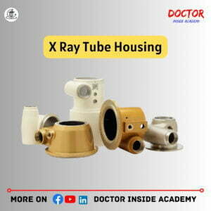
Role of X Ray Tube Housing
X Ray Tube Housing supports, protects, and insulates the X-ray tube from the external environment.
X Ray Tube Housing is made up of lead and this helps to protect against radiation leakage and pass the X-rays only through the window.
X Ray Tube Housing helps in the proper mounting and positioning of x ray tubes.
Main Function of X Ray Tube Housing
Radiation Protection
X ray tube housing provides radiation shielding and directs radiation toward the desired body or objects.
X ray tube housing is mostly made up of lead material.
Electrical Protection
X ray tube housing acts as an electric insulator, preventing electric shocks.
Thermal Protection
X ray tube housing has a cooling mechanism, that keeps undesired heat out from the x ray fastly and maintains adequate temperature within the x ray tube.
Physical Production
X ray housing provides protection and physical support to the x ray tube and keeps the material in the tube aligned also.
x-ray tube shielding is filled with coolants that act as an electric insulator and prevent electric shock shields from being earthed.
It acts as a cooling medium and one of its main properties is it can expand when heat is provided.
That’s why the expansion below is used to keep this aligned and in proper assembly.
The effectiveness of X-Ray shows housing is proper and must follow the rules of AERB.
Hence, X ray tube housing is very important in x ray tube to perform well and provide insulation, avoid electric shocks also, and keep all accessories part of x ray tube assembled.
X Ray Filters
As we know, x-ray tubes are known to produce X-rays in different energy ranges,
These are high-energy photons or low-energy photons,
These high-energy photons are useful and are described in X-ray imaging because high-energy photons pass through tissue and bone and hit the image receptors.

On the other hand, low-energy photons are mostly scattered or absorbed by human tissue,
These scattered radiations are useless and do not contribute to imaging, and the radiation absorbed by the body only increases the patient’s radiation dose,
So, a new method is introduced to get rid of these low-energy photons and get a better image, this is known as his X-ray filters,
X-ray filters are metal sheets placed in front of the X-ray tube to absorb low-power radiation and provide a better image,
The process of removing low-energy photons and reducing the patient’s dose is called filtering.
The use of metal sheets to remove low-energy photons is called filtration.
Without an X-ray filter, this low-power radiation is absorbed by the patient’s tissue and does not participate in X-ray imaging, it just adds to the patient’s radiation,
After the x-ray filtration of lower energy x-rays, a change takes place in the x-ray spectrum and this is known as beam hardening.
The unit of filtration is expressed in mm aluminum equivalent.
Advantages of X Ray Filters
- X Ray Filters absorb low-energy photons,
- These reduce the unnecessary patient radiation dose,
- These Increases the quality of radiograph.
Disadvantages of X Ray Filters
- X ray filters decrease the intensity of X-ray photons,
- These increase the time required for exposure,
- These absorb primary X-rays.
Main Types of Filters
Based on types of X-ray filtration used in X-ray modalities are following;

Inherent Filters
inherent filtration performs its actions to main x-ray output at the optimum level of exposure.
- Inherent filters installed in X-ray tube components such as – windows, glass enclosures, cooling oil,
- The thickness of inherent filters is 0.5mm aluminum equivalent,
Added Filters
Added filters are installed manually and not in the manufacturing process of the x ray tube.
- These are from outside the x ray tube or enclosure;
- Added filters act as Collimator;
- It is made of aluminum, copper, etc.;
- The thickness of added filters is 1-1.5 mm aluminum comparison.
Why do we use Copper and Aluminum?
The main reason for using copper and aluminum in x-ray filters is their atomic number.
- The atomic number of copper is 29,
- The atomic number of aluminum is 13,
* Low atomic number metals are the best low-energy photon absorber, The weight is also less; so, X-ray tubes are lightweight and easy to handle.
Total Filtration
The total filtration is the combination of Inherent filtration and Additional filtration.
*AS Per US Guidelines, x-ray tubes require at least 2.5 mm Of Aluminum to operate x-ray tube at 70 KvP,
In Mammography, Molybdenum filters are used because they reduce the number of high-energy X-rays and improve the contrast of the soft tissues of the breast,
The Molybdenum filter is 0.03 mm,
Filtration reduces the intensity, but not that much,
Since low-energy photons are removed from a polychromatic beam, the use of filters to alter the shape of the beam spectrum is known as beam hardening.
With filtering, the X-ray energy increases, and the penetrating power is stronger.
Other Types of Filters
There are many types of x ray filters used in x ray machines, We discussed many above and a few other types of x-ray filters will be explained below.

Compensation Filters
The human body has different tissue densities and these tissue densities vary in attenuation of X-rays, and this may result in under-exposed or overexposed radiographic images.
Hence, compensate filters are used to produce uniform densities in the radiographic images.
These are available in different shapes and sizes and are selected based on which body area is imaged.
Types of Compensation Filters
Compensation filters are also divided further based on their categorisation, which are the followings;
Boomerang Filters
- These are used during shoulder radiographs,
- These balance soft tissue density,
Trough Filters
- These are used during chest radiographs.
- These are used to fix to collimator of the tube,
Wedge Filters
- Also fixed to the collimator.
- This maintains the ratio according to the thickness.
Ferlic Filters
- These are used in x ray filtration.
Flattening Filters
- These are also used in x ray filtration and are the types of compensation filters.
Compound Filters
- Made up of two or more layers of different materials.
Thoraeus Filters
These are made up of three layers containing tin, copper, and aluminum,
- Copper thickness is 0.1 mm to 0.9mm and the aluminum filter is 1.0mm thick,
- These layers absorb photons created by the previous layer.
K Edge Filters
- K edge filters are based upon the principle of the k edge of elements,
- These decrease low-energy photons. It results in decreases in patient absorbed dose.
- These also decrease high-energy photons at appropriate levels to improve image contrast.
Final Words
In this Chapter 3 of X Ray Course, we learned about focal spot sizes, the line focus principle, different types of filters, and the difference between inherent and added filters.
I hope you enjoyed this article and get towards your academic career and you can connect with us on all social media.
Disclaimer
The information provided in this article is only for educational purposes. We keep the information up to date and accurate based on different studies, you can use this article content with proper mentioning, and misuse of the content is strictly prohibited.
The article content is based on learning, experiences, and research performed by the author and we don’t provide specific guidance and recommendations at an individual level.
This article may contain external links to other websites or resources. We have no control over the concrete availability.
Don’t follow any medical advice given on this blog, without consulting with your doctor or physicians first.